Microcontroller
Teensy Setup
The Teensy 3.2 microcontroller (MCU) is used to get the ticks from the encoders attached to the motors and send this information (counts) as a message over the /diffbot/ticks_left
and /diffbot/ticks_right ropics. For this rosserial is running on the Teensy MCU which allows it to create a node on the Teensy that can communicate with
the ROS Master running on the Raspberry Pi.
To setup rosserial on the work PC and the Raspberry Pi the following package has to be installed:
1 | |
To program the Teensy board with the work PC the Arduino IDE with the Teensyduino add-on can be used. Other options are to use PlatformIO plugin for VSCode. How to install the Arduino IDE and Teensyduino is listed in the instructions on the Teensy website. Here the instructions to setup Teensyduino in Linux are listed:
- Download the Linux udev rules (link at the top of this page) and copy the file to /etc/udev/rules.d.
sudo cp 49-teensy.rules /etc/udev/rules.d/- Download and extract one of Arduino's Linux packages. Note: Arduino from Linux distro packages is not supported.
- Download the corresponding Teensyduino installer.
- Run the installer by adding execute permission and then execute it.
chmod 755 TeensyduinoInstall.linux64./TeensyduinoInstall.linux64
The first step can be used on the work PC and the Raspberry Pi to enable the USB communication with the Teensy board. Step two of these instructions are only necessary on the work PC to actually program the Teensy board.
Note
Make sure to download the Arduino IDE from the website and don't install it from the Ubuntu repositories.
The following video shows installation process, more instructions to setup the Arduino IDE can be found in the ROS wiki.
To check if the connection to the Teensy board works use these commands on the Raspberry Pi:
1 2 3 4 5 | |
And to see on which serial port it is connected use:
1 2 | |
If the output is empty it might be the case that the board is connected to another port like ttyUSB0.
Encoder Program
When installing Teensyduino new example programs are provided. One of them is to test Encoders. The code for the motor encoders uses it as basis together with a pubsub example from rosserial:
TODO link to code encoders.ino
After the program is flashed to the Teensy board it can be tested with the following procedure:
- Start a ROS master by executing
roscorein a new terminal. - Create a rosserial node using
rosserial_pythonpackage:
1 2 3 4 5 6 7 8 9 | |
In case of the following error, probably the wrong program is flashed to the Teensy board:
1 | |
Note
Note that the rosserial node needs to be stopped to flash new sketches to the Teensy board.
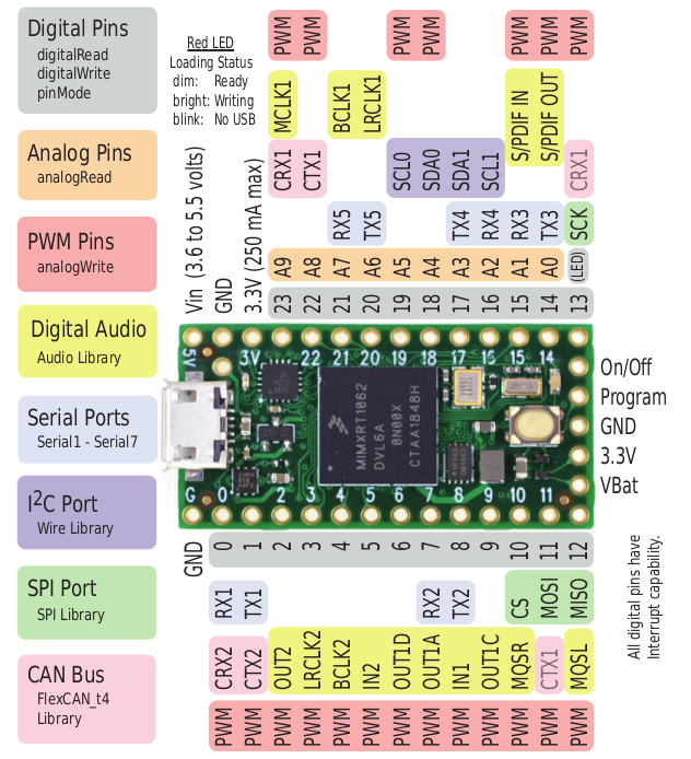
Each DG01D-E motor has two signal pins for its built-in encoder. For these, the Teensy pins 5, 6 are used for the left encoder and 7, 8 are used for the right one, see also the Teensy pinout.
The bread board view of Fritzing shows the connection schematic and is shown for both models in the following:


With one motor encoder connected to pins 5, 6, echo the /encoder_ticks topic:
1 | |
Rotating a wheel attached to the motor shaft 360 degree (one full turn) will increase the first value of the encoders array:
1 2 3 4 5 6 7 8 9 10 11 12 13 14 15 16 17 18 19 20 21 22 23 24 25 26 27 28 29 30 31 32 33 34 35 36 37 38 39 40 | |
The found value 540 for a full turn of the wheel is important for the hardware interface.
Base Controller
If you are working with Remo the recommende way is to use base_controller from diffbot_base/scripts instead of the encoders.ino.
Build instructions using Visual Studio Code including the PlatformIO plugin are shown in the following video:
When using base_controller you should use the low level PID controllers running on the MCU.