Autonomous Differential Drive Mobile Robot - Base Package
DiffBot Base Package
This package contains the so called hardware interface of DiffBot which represents the real hardware in software to work with ROS Control.

This package contains the platform-specific code for the base controller component required by the ROS Navigation Stack. It consists of the firmware based on rosserial
for the Teensy MCU and the C++ node running on the SBC that instantiates the
ROS Control hardware interface, which includes the controller_manager control loop
for the real robot.
The low-level base_controller component reads the encoder ticks from the hardware,
calculates angular joint positions and velocities, and publishes them to the
ROS Control hardware interface. Making use of this interface makes it possible
to use the diff_drive_controller package
from ROS Control. It provides a controller (DiffDriveController) for a differential
drive mobile base that computes target joint velocities from commands received by either
a teleop node or the ROS Navigation Stack. The computed target joint velocities are
forwarded to the low-level base controller, where they are compared to the measured
velocities to compute suitable motor PWM signals using two separate PID controllers,
one for each motor.
Another part of this package is a launch file that will
- Load the robot description from
diffbot_descriptionto the paramter server - Run the hardware interface of this package
diffbot_base - Load the controller configuration yaml from the
diffbot_controlpackage to the parameter server - Load the controllers with the controller manager
- Load the value of the encoder resolution to the parameter server
Low-Level vs High-Level PID
There exist (at least) two commonly used approaches to control a robot base.
The difference between the two presented approaches here is where the PID controller(s) that control each motor are kept. One possibility is to run these PIDs on the high level hardware interface on the SBC and sending the computed output commands to a motor driver node. Another option operates the PIDs on the low-level microcontroller hardware. For DiffBot these approaches are refered to as
- High-Level PIDs running on the hardware interface on the SBC
- Low-Level PIDs running on the firmware of the microcontroller
The DiffBot project initially used the PID controllers in the high level hardware interface. From release 1.0.0 on two low-level PIDs are operating on the low-level base controller hardware.
This section focuses on the current approach (low-level PIDs). The previous approach (high-level PID) is documented in High-Level Approach.
Developing a low-level controller firmware and a high-level ROS Control hardware interface for a differential drive robot
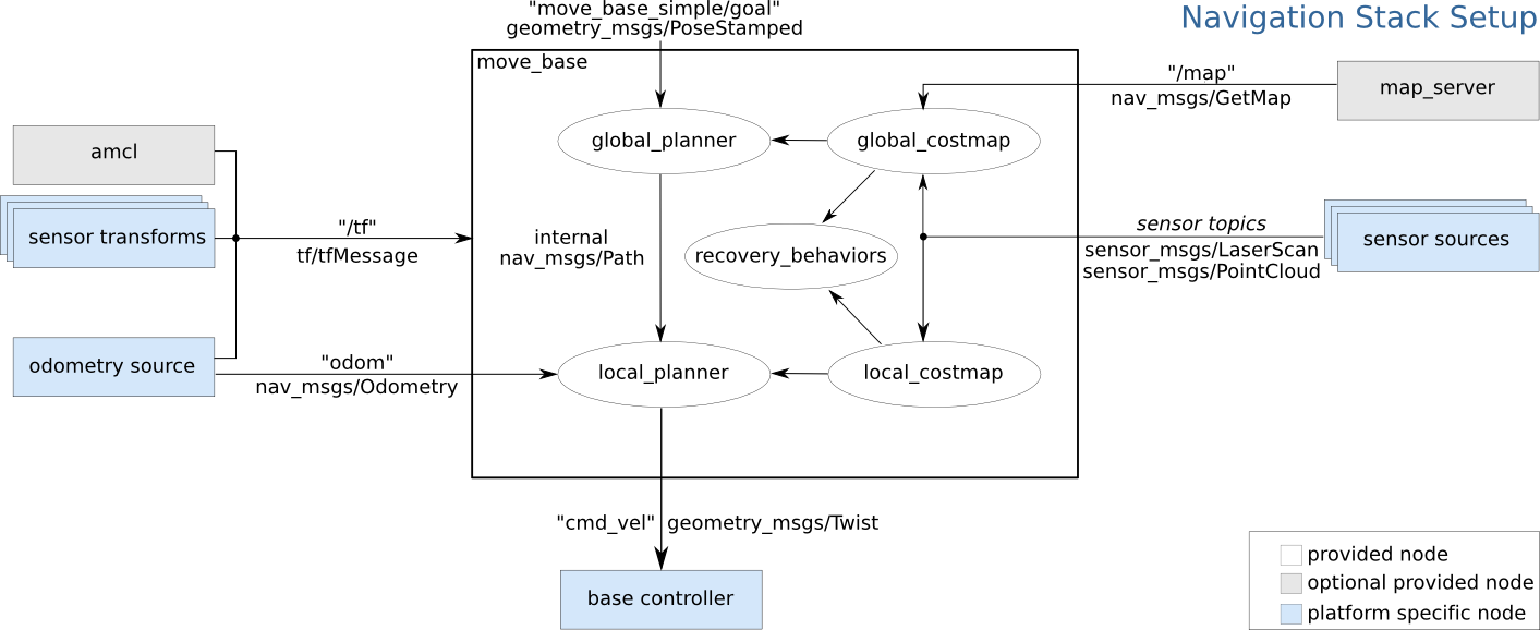
In the following two sections, the base controller, mentioned in the Navigation Stack, will be developed.
For DiffBot/Remo, this platform-specific node is split into two software components.
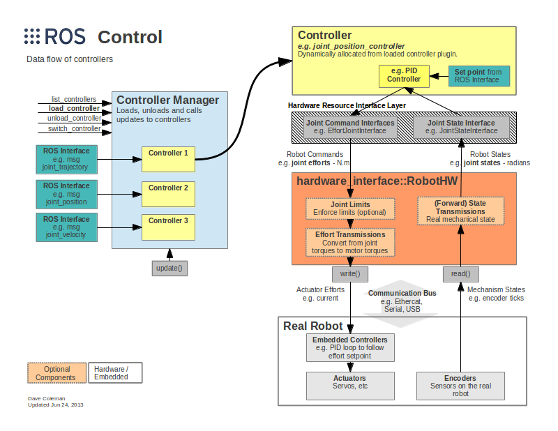
The first component is the high-level diffbot::DiffBotHWInterface that
inherits from hardware_interface::RobotHW, acting as an interface between
robot hardware and the packages of ROS Control that communicate with the
Navigation Stack and provide
diff_drive_controller – one of
many available controllers from ROS Control. With the gazebo_ros_control
plugin, the same controller including its configuration can be used in
simulation and the real robot.
An overview of ROS Control in simulation and the real world is given in the following figure (http://gazebosim.org/tutorials/?tut=ros_control):
The second component is the low-level base controller that measures angular wheel joint positions and velocities and applies the commands from the high-level interface to the wheel joints. The following figure shows the communication between the two components:
The low-level base controller uses two PID controllers to compute PWM signals
for each motor based on the error between measured and target wheel velocities.
RobotHW receives measured joint states (angular position (rad) and angular
velocity (rad/s)) from which it updates its joint values. With these measured
velocities and the desired command velocity (geometry_msgs/Twist message on
the cmd_vel topic), from the Navigation Stack, the diff_drive_controller
computes the target angular velocities for both wheel joints using the
mathematical equations of a differential drive robot. This controller works with
continuous wheel joints through a VelocityJointInterface class. The computed
target commands are then published within the high-level hardware interface
inside the robot's RobotHW::write method. Additionally, the controller
computes and publishes the odometry on the odom topic (nav_msgs/Odometry) and
the transform from odom to base_footprint.
Having explained the two components of the base controller, the low-level firmware is implemented first. The high-level hardware interface follows the next section.
But before this an introduction to the PID controllers are given in PID Controllers.
diffbot_base Package
The diffbot_base package was created with catkin-tools:
1 2 3 4 5 6 7 | |
To work with this package the specified dependencies must be installed either using the available Ubuntu/Debian packages for ROS Noetic or they have to be built from source first. The following table lists the dependencies should have been install during the initial setup phase. These dependencies are not already part of the ROS Noetic desktop full installation but required for the diffbot_base package.
Note
Follow the instructions at ROS Noetic Setup on how to setup ROS and the obtain (system) dependencies section on how to install all required dependencies. Performing these steps avoids installing any dependencies manually.
| Dependency | Source | Ubuntu/Debian Package |
|---|---|---|
rosparam_shortcuts |
https://github.com/PickNikRobotics/rosparam_shortcuts | ros-noetic-rosparam-shortcuts |
hardware_interface |
https://github.com/ros-controls/ros_control | ros-noetic-ros-control |
diff_drive_controller |
https://github.com/ros-controls/ros_controllers | ros-noetic-ros-controllers |
