IMU: Bosch BNO055
An inertial measurement unit (IMU) measures how the robot turns and accelerates: its gyroscope measures the angular velocity about three axes, its accelerometer the specific force, the acceleration minus gravity, which at rest reads about +9.8 m/s² upwards. DiffBot and Remo use the Adafruit 9-DOF Absolute Orientation IMU Fusion Breakout with Bosch's BNO055: an accelerometer, a gyroscope and a magnetometer in one package, with a processor that fuses them. Both robots use the same board, which is moved from one robot to the other.
Why the accelerometer reads +9.8 m/s² upward at rest
The accelerometer contains a tiny suspended mass. When the robot rests on the floor, the floor supports the robot, and the sensor's suspension supports that mass against gravity. It's like the upward force you feel from the floor on your feet.
The reading is the specific force, also called proper acceleration: the acceleration relative to free fall. With z pointing upward, gravity is −9.81 m/s². So the resting sensor reads 0 − (−9.81) = +9.81 m/s², although the robot's velocity doesn't change. In ideal free fall, the sensor and its mass fall together, and the reading is zero.
Analog Devices explains the mass on its springs and how its movement is measured. REP 145, the ROS convention for IMU data, specifies +g on an upward axis at rest.
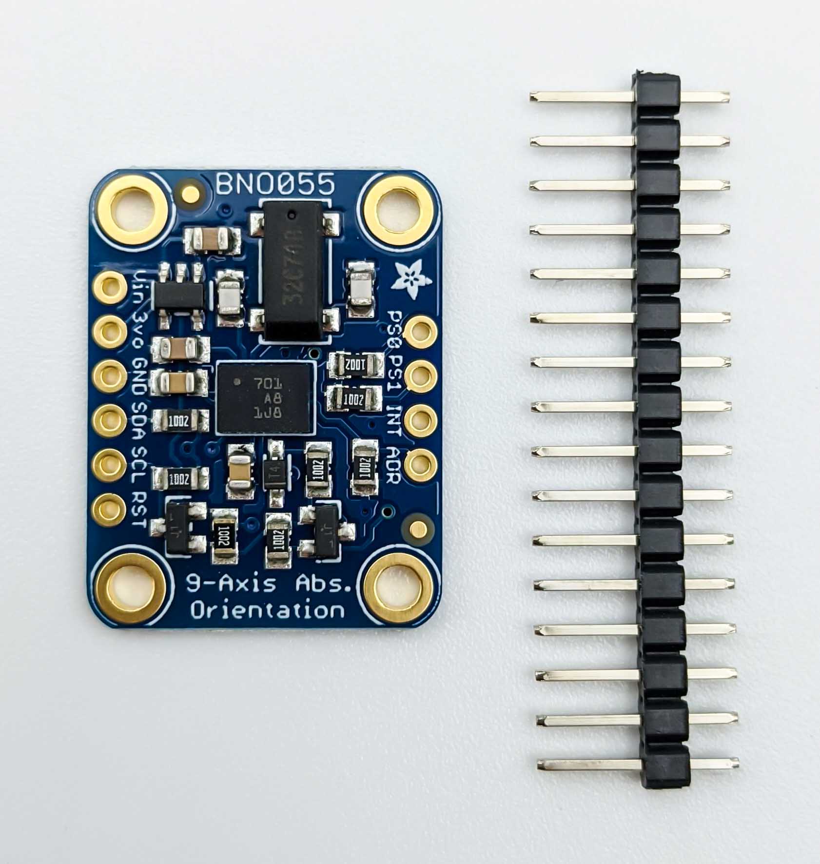
The robot uses one value from it: the yaw rate, the angular velocity about the upward axis. The EKF on the robot's computer fuses it with the wheel odometry, which, on its own, estimates turns less well. The BNO055 sits on the Teensy's I2C bus, and the Teensy's firmware publishes its measurements over rosserial.
Checked on Remo
The firmware passed the bench checks on Remo with the wheels off the ground, using both a Teensy 3.2 and Remo's own Teensy 4.0 (Teensy 4.0 results). A tilt test established the board's orientation. Remo's model includes that orientation and the separately checked position on the breadboard. On DiffBot, the IMU's mounting still needs to be measured, and the firmware checked on DiffBot itself. The EKF still needs a test with the real IMU.
Wiring to the Teensy
The BNO055 shares the Teensy's first I2C bus, Wire, with the motor driver (Adafruit Motor FeatherWing). On the Teensy 4.0 and 3.2, Wire uses pin 18 for SDA and pin 19 for SCL (PJRC: Wire library):
| BNO055 breakout | Teensy | Note |
|---|---|---|
| VIN | 3.3V | The breakout takes 3.3 to 5 V. 3.3 V is the Teensy's logic level |
| GND | GND | |
| SDA | 18 (SDA) | The breakout has a 10 kΩ pull-up resistor on SDA and SCL |
| SCL | 19 (SCL) | |
| ADR | not connected | I2C address 0x28. Connected to 3.3 V: 0x29, then set IMU_BNO055_ADDRESS |
The other pins (3Vo, RST, INT, PS0, PS1) stay unconnected. 3Vo is the breakout's 3.3 V output. Adafruit's pinouts page describes all of them. The motor driver's address is 0x60, so the two don't collide.
What the firmware publishes
The firmware in diffbot_firmware reads the BNO055 in its IMU fusion mode (accelerometer and gyroscope, without the magnetometer, called IMUPLUS in Bosch's and Adafruit's libraries) and publishes /diffbot/imu/data_raw, a sensor_msgs/Imu message, at 50 Hz:
| Field | Content |
|---|---|
header.frame_id |
imu_link: the sensor's own axes. The robot's URDF places this frame where the board sits |
header.stamp |
ROS time before the read |
angular_velocity |
rad/s, from the gyroscope |
linear_acceleration |
m/s², the specific force, including gravity |
orientation |
not provided: orientation_covariance[0] is −1, which REP 145 defines as "no data" for a field |
| covariances | diagonal starting values: 4 · 10⁻⁴ (rad/s)² and 10⁻² (m/s²)². At rest, the bench checks measured much less, but driving adds vibration and drift |
The chip's own orientation estimate isn't read: the EKF uses only the angular velocity. The topic's name is REP 145's for accelerometer and gyroscope data without an orientation.
The settings are in diffbot_base_config.h: IMU_BNO055_ADDRESS and IMU_PUBLISHER_CONFIG. The second is one value of the type ImuPublisherConfig from imu_config.h, with these fields:
| Field | Robot's value | What it's for |
|---|---|---|
enabled |
true |
false for a robot without an IMU: no topic, no I2C traffic |
period_ms |
20 | The sampling period, 50 Hz |
retry_ms |
10000 | Look for a missing or failed IMU again after 10 s |
read_budget_us |
10000 | Drop a sample whose read took longer than 10 ms |
frame_id |
"imu_link" |
header.frame_id |
angular_velocity_variance |
4.0e-4 | (rad/s)², on the covariance's diagonal |
linear_acceleration_variance |
1.0e-2 | (m/s²)², on the covariance's diagonal |
The compiler checks the field types. A build-time check (static_assert) rejects invalid values, such as a read budget as long as the sampling period. The unit tests pass settings of their own. The comment in the configuration header explains the covariances' starting values with the datasheet's noise and offsets.
How the firmware reads it
lib/imu has a small driver of its own for the BNO055, instead of Adafruit's library, so that every I2C transfer is checked and the start-up's waits don't hold up the firmware's loop:
- The start-up doesn't block the motor control. A reset of the chip takes about 650 ms, and each switch of its operating mode up to 19 ms (Bosch's datasheet). The driver goes through the steps as a state machine: configuration mode, reset, settings written and read back, IMU mode, until the chip reports that its fusion runs. Instead of sleeping through those times, each pass through the firmware's loop checks whether the next step is due and does it. Most steps take one or two transfers. The step that writes the settings and reads them back takes 14, about 4 ms, once per start-up. The transfers themselves are synchronous: the loop waits while one runs, about 0.3 ms for one register and about 3 ms for a whole sample (26 bytes) at I2C's standard clock of 100 kHz. The waits for the chip to finish resetting and start its fusion have deadlines. If either wait reaches its deadline, the driver fails the start-up on the next loop pass. The firmware tries again after
retry_ms. On Remo, the control loop kept its 20 Hz while the IMU was unplugged (bench checks). - A sample is published only if it's good: the read succeeded and took at most
read_budget_us(10 ms: a later result is dropped, but the budget can't cut a transfer short), the chip still is in IMU mode with the right units and its fusion runs. A stalled or unplugged IMU stops the topic instead of repeating old values with new stamps. After ten failed reads in a row, the firmware starts the chip again. A missing IMU is looked for again everyretry_ms(10 s). The robot drives without an IMU, too. - Stamps are ROS time, which rosserial takes from the robot's computer: the Teensy's clock is synchronized with it every few seconds. Until the first synchronization after a connection, the firmware publishes nothing, because a stamp would carry the Teensy's uptime instead of ROS time.
- The 50 Hz rate counts on the Teensy's own clock (
millis()), so it doesn't change when ROS time jumps, for example when the Teensy connects to a computer whose clock is earlier.
Unit tests on the PC: .docker/firmware/run.sh pio test -e native, from the root folder of the diffbot repository, runs the tests in diffbot_firmware/test in the firmware container (Running the checks locally). They run the driver, the bus code, the time-sync check and the publisher with a fake sensor, I2C bus, serial port and clock, and with rosserial's own message parser. CI runs them in the firmware workflow (Testing and CI). They check the logic, not the hardware.
Bench checks
With the bringup running on the robot and its wheels off the ground:
- Rate and stamps:
rostopic hz /diffbot/imu/data_rawshows about 50 Hz, and the stamps inrostopic echo /diffbot/imu/data_raware the current ROS time. - Axes and signs: with the robot level and still, the accelerometer's upward axis reads about +9.8 m/s². Turning the robot counterclockwise by hand, seen from above, gives a positive angular velocity about that axis (REP 103). These checks identify the upward axis and its sign. To check the horizontal axes, lift the robot's front slightly and hold the robot still while reading the acceleration. Return the robot to level, then lift the left side and hold still again. For sensor axes aligned with the robot's directions, a horizontal axis pointing toward the raised side reads positive. An axis pointing the opposite way reads negative. On Remo, raising the front gives positive y and raising the left side gives negative x. These checks establish the orientation of
imu_linkin the URDF. The mounting position must be checked separately. - Noise and bias: a stationary recording of a few minutes (
rosbag record /diffbot/imu/data_raw) gives the gyroscope's bias and variance at 50 Hz, to replace the covariances' starting values. - Faults: unplugging the IMU stops the topic and logs a warning. While it stays missing, each retry logs another warning. The wheels keep following commands. Plugged back in, it's found at the next try, at most
retry_ms(10 s) later, and publishes again after its start-up, which takes about another second. The control loop keeps its rate during all this. The firmware's command timeout keeps working: after 1 s without a wheel command, it stops driving the motors and resets the wheels' PIDs (COMMAND_TIMEOUT_MS,eStop()). - Timing: the control loop keeps its rate with the IMU running, for example
rostopic hz /diffbot/measured_joint_states.
Remo was checked on 2026-10-31 with firmware 1a3b547 built for the Teensy 3.2, and the ROS commands ran in the robot container. The BNO055 used SDA 18 and SCL 19, with VIN supplied by the Raspberry Pi's 3.3 V (evidence, checklist diffbot#169). The bias is the average reading at rest. The standard deviation is the spread of the readings around that average.
| Check | Result |
|---|---|
| Rate and stamps | 50.0 Hz. 180 s at rest: 8,986 messages, gaps between 14 and 27 ms. Stamps in current ROS time, also after rosserial reconnected |
| Axes and signs | At rest in this recording, z reads about +9.7 m/s². Turning left, angular_velocity.z is positive. How the board is turned about z came from a later tilt test, below |
| Noise and bias at rest | Gyroscope: bias below 0.0001 rad/s, variance 2 to 6 · 10⁻⁷ (rad/s)². The standard deviation is 0.0005 to 0.0008 rad/s, below the output step of 1/900 rad/s. Accelerometer: variance 4 to 8 · 10⁻⁴ (m/s²)² |
| Faults | Unplugged while the wheels turned at 9 rad/s: a warning after ten failed reads (0.2 s), and the wheels kept their speed. Plugged back in: found again within 10 s. With SDA and SCL swapped, it stayed "not found", without blocking the firmware |
| Timing | measured_joint_states at 20.0 Hz with the IMU running |
A tilt test on 2026-11-05 checked the BNO055's axes on Remo using the Teensy 4.0. With the front held raised, the average y acceleration was +3.21 m/s². With the left side held raised, the average x acceleration was −7.24 m/s². The z acceleration remained positive during both tilts and was close to +9.8 m/s² with the robot level. These readings show that the board's y axis points forward, its x axis points right, and its z axis points up when Remo is level. The corresponding URDF orientation is imu_rpy="0 0 -1.5707963", a −90° rotation about chassis_link's z axis. The chip's pin-1 dot sits at the board's front right corner, which with the datasheet's default axes, placement P1 (BNO055 datasheet, page 27) gives the same. Remo's model has this orientation and the checked position on Remo's Raspberry Pi deck (remo.urdf.xacro, lines 12–27 in remo_description 2.5.0). The IMU's header pins sit in the breadboard, and imu_link lies about 7.6 cm behind the wheel axle and 2.34 cm left of the robot's center line.
The covariances stay at their starting values for now: driving adds vibration and drift, which a recording at rest doesn't show. The evidence has the numbers and log excerpts, diffbot#169 the full checklist.
To try the breakout separately with an Arduino, see Adafruit's Arduino guide for wiring, library installation and example programs.
Trying the breakout on the Raspberry Pi
To check a breakout on its own, it can also be connected to the Raspberry Pi's I2C pins (pinout): VIN to 3.3 V, GND to GND, SDA to SDA, SCL to SCL. Adafruit's guide reads it with Python and its CircuitPython library: first prepare the Pi for it (I2C on, the Blinka library), then slow down the Pi's I2C clock, which the BNO055 needs because it stretches the clock, and then run the BNO055 example.
ros-imu-bno055 is a C++ driver for ROS 1 and ROS 2 that reads the BNO055 over I2C. The project's README says the driver should work on a Raspberry Pi 5, or on an older Pi using software I2C. The author has not tested the slower-clock workaround with this driver. DiffBot and Remo read the IMU on the Teensy. ros-imu-bno055 has not been tested with either robot.
Comments
Comments are GitHub Discussions, shown with giscus. Loading them connects to giscus.app (hosted by Vercel, USA) and GitHub (USA); you need a GitHub account to comment.